> Complete documentation index: [llms.txt](/llms.txt). Markdown versions of all pages are available by appending `.md` to page URLs.
# Binho Supernova: Hardware reference
> Ports and power domains, electrical ratings, target voltage, pinout and status LEDs of the Binho Supernova.
Ports and power domains, electrical ratings, target voltage, pinout and status LEDs of the Binho Supernova.
## Ports and Power Domains
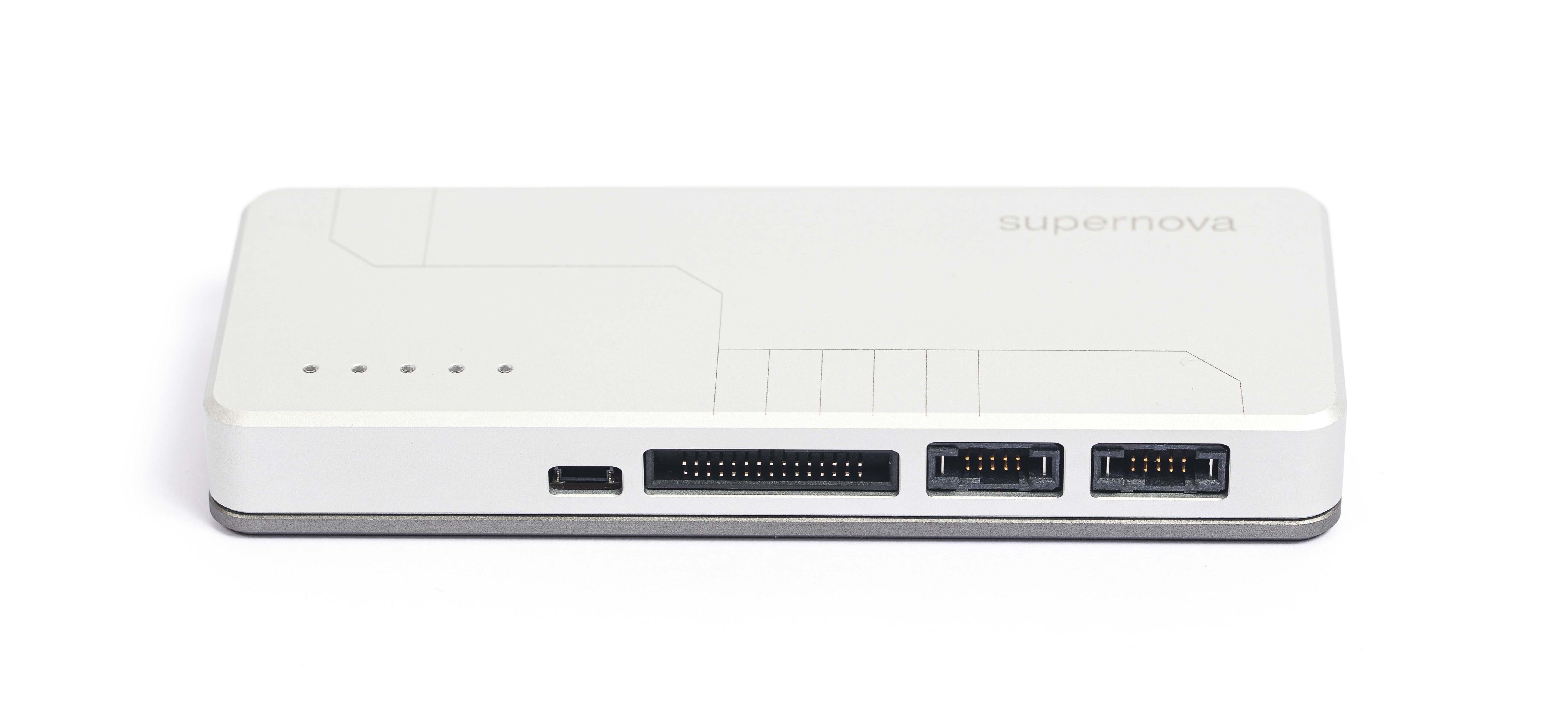
Supernova's ports
The Supernova connects to the computer over **USB-C** (USB 2.0 Full Speed, 12 Mbps), which also powers it. It enumerates as a USB HID device plus a USB CDC virtual COM port, so no driver install is needed. On Linux, add a one-time USB permission rule: see [Solving USB Connection Issues on Linux](/support/troubleshooting/solving-usb-connection-issues-on-linux/).
The front has four ports on three power domains. The two I3C ports cannot be used at the same time:
| Port | Connector | Signals | Power domain | Voltage |
| --- | --- | --- | --- | --- |
| **I3C High Voltage (HV)** | 2x5 TigerEye | I3C, legacy I2C, SMBus | I3C HV | 1.2 V to 3.3 V |
| **I3C Low Voltage (LV)** | 2x5 TigerEye | I3C, legacy I2C | I3C LV | 0.8 V to 1.2 V |
| **Multifunction** | 2x15, 1.27 mm IDC | I2C, SPI, UART, GPIO | Multifunction | 1.2 V to 3.3 V |
| **Dedicated I2C** | 4-pin JST SH (Qwiic) | I2C (same bus as the Multifunction port) | Multifunction | 1.2 V to 3.3 V |
* Only one I3C port is active at a time. In PyCosmicSDK the voltage that is set picks the port: 800–1199 mV drives the LV port, 1200–3300 mV the HV port.
* The active I3C port and the Multifunction domain are set independently. A 1.0 V I3C bus can run next to a 1.8 V SPI bus. I2C, SPI, UART and GPIO share the Multifunction domain, so they always run at the same voltage.
* All domains share one ground, which is also the host PC's USB ground.
* Each domain's target voltage (VTARG) pin either **outputs** power to an unpowered target, or acts as the **logic-level reference** for a self-powered target.
## Electrical Ratings
From the datasheet (revision 1.6), recommended operating conditions:
| Domain | Voltage (in or out) | Output current, typ / max |
| --- | --- | --- |
| I3C HV | 1.2 V to 3.3 V | 100 / 200 mA |
| I3C LV | 0.8 V to 1.2 V | 100 / 350 mA |
| Multifunction | 1.2 V to 3.3 V | 100 / 200 mA |
USB input: 4.5 V to 5.5 V, 500 mA typical. Operating temperature 0 °C to 70 °C. ESD rating ±4 kV.
:::danger
Absolute maximum voltage on signal pins: 3.6 V on the I3C HV port, 2.5 V on the I3C LV port, 4.2 V on the Multifunction and Dedicated I2C ports. Exceeding these can damage the adapter.
:::
## Target Voltage (VTARG)
Set each rail from Mission Control 3 or the SDKs before bringing a bus up, so pull-ups and level shifters match the target. Firmware behaviour to know:
* **Self-powered targets.** Use the SDK's `use_external_voltage()` (or the equivalent in Mission Control 3) so the adapter follows the target's VTARG instead of driving it. With firmware 4.6.x and earlier, setting a voltage on a port the target already powers connects the adapter's rail to the target's supply.
* **After a reset or firmware update.** With firmware 4.6.x and earlier, a rail that was saved at one voltage and later set to 0 V can come back at about 3.3 V. Unplugging and replugging USB loads the saved voltage correctly. Disconnect sensitive targets before updating firmware on 4.6.x or earlier.
* **Rail off.** With firmware 4.6.0 and later, setting the Multifunction rail to 0 V also stops the SPI, UART and GPIO pins from driving, so an unpowered target is not fed through its I/O. On 4.5.1 and earlier, return outputs to inputs before switching the rail off. With firmware 4.6.x and earlier, the I2C pull-ups stay powered with the rail at 0 V and can partly power an unpowered target through SDA and SCL: disable the pull-ups or disconnect the target first.
* **I3C HV accuracy.** Firmware 4.6.0 and later trims the HV rail closed-loop: measured within −7 mV to +2 mV across 1200–3250 mV. A set takes about 550 ms. On older firmware a 1200 mV request could read about 1075–1094 mV.
## Pinout Guide
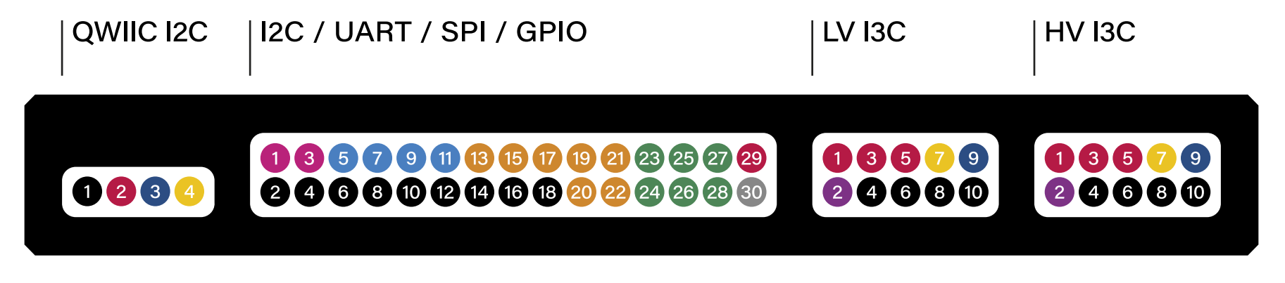
### Dedicated I2C Port (Qwiic)
| 1 - GND | 2 - VTARG | 3 - SDA | 4 - SCL |
| ------- | ----------- | ------- | ------- |
### Multifunction Port (I2C / UART / SPI / GPIO)
Even pins 2 to 18 are GND.
| Pin | Signal | Pin | Signal |
| --- | --- | --- | --- |
| 1 | I2C SCL | 3 | I2C SDA |
| 5 | UART RX | 7 | UART TX |
| 9 | UART RTS | 11 | UART CTS |
| 13 | SPI MOSI (SDO) | 15 | SPI MISO (SDI) |
| 17 | SPI CLK | 19 | SPI CS0 |
| 20 | SPI CS1 | 21 | SPI CS2 |
| 22 | SPI CS3 | 23 | GPIO 1 |
| 24 | GPIO 2 | 25 | GPIO 3 |
| 26 | GPIO 4 | 27 | GPIO 5 |
| 28 | GPIO 6 | 29 | VTARG |
| 30 | Not connected (reserved) | | |
### I3C Ports (LV and HV, Same Pinout)
| 1 - VTARG | 2 - DETECT | 3 - VTARG | 4 - GND |
| ----------- | ---------- | ----------- | ------- |
| 5 - VTARG | 6 - GND | 7 - SCL | 8 - GND |
| 9 - SDA | 10 - GND | | |
DETECT identifies the plugged-in harness (the I3C harness or the Qwiic adapter board). Do not connect it to the circuit.
:::note
I3C is sensitive to wiring. Use the supplied I3C harness, or the I3C-to-Qwiic adapter board with the shortest possible leads.
:::
## Status LEDs
The Supernova has 5 RGB LEDs.
* **Idle:** the LEDs cycle between green and blue.
* **Command received:** the cycle pauses for 30 seconds.
* **Fourth LED:** lights when the Supernova receives a USB message.
* **Fifth LED:** lights when it sends a response to the host.