> Complete documentation index: [llms.txt](/llms.txt). Markdown versions of all pages are available by appending `.md` to page URLs.

# I3C

> Use the I3C command panel in Mission Control 2: available devices, clock settings, bus voltage, private transactions and Common Command Code transfers.

:::caution
**Mission Control 2: legacy, for the Binho Nova.** For the Binho Supernova, the Binho Pulsar and the Binho Atira, use [Mission Control 3](/software/legacy/mission-control-2/).

:::

I3C (_Improved Inter-Integrated Circuit_) is the successor to I2C and is backward compatible with it. It adds Dynamic Address Assignment, higher data rates, CCC commands, multi-controller support, Hot-Join and removal events and In-Band Interrupts (IBIs). The Binho Supernova supports I3C.

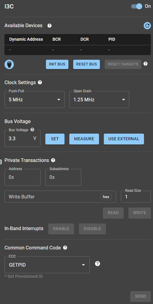
The I3C command panel is organized in five segments: Available Devices, Clock Settings, Bus Voltage, Private Transactions, and Common Command Code transfers.

<figure><img src="/files/I3C_panel.png" alt=""><figcaption><p>I3C command panel.</p></figcaption></figure>

## Available Devices

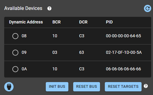
When the INIT BUS button is pressed, the Binho Supernova initializes the bus, sets the bus voltage and assigns dynamic addresses to the target devices. In this process, the targets send their BCR, DCR and PID to the Controller, so it can identify them and assign them the dynamic addresses. After this is concluded, all target devices are listed up in the Available Devices table:

<figure><img src="/files/I3C_table.png" alt=""><figcaption><p>Available Devices segment</p></figcaption></figure>

The Available Devices panel also offers other functionalities that allows, for example, resetting the bus, resetting targets (via the Target Reset Pattern specified in the I3C protocol), obtaining the I3C connector status and also refreshing the targets table (managed by our SDK).

## Clock Settings

<figure><img src="/files/image%20(31).png" alt=""><figcaption><p>Clock Settings sub-panel.</p></figcaption></figure>

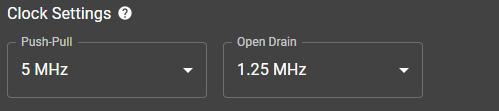
In the Clock Settings segment the user can configure two different clock frequencies:

<table><thead><tr><th width="228">Parameter</th><th width="234">Admited values</th><th>Comment</th></tr></thead><tbody><tr><td>Push-Pull</td><td>3.75 to 12.5 MHz</td><td>6 possible values</td></tr><tr><td>Open Drain</td><td>0.1 to 4.17 MHz</td><td>7 possible values</td></tr></tbody></table>

Notes:

* **Push-Pull Clock**: Standard for regular transactions like Reads and Writes.
* **Open Drain Clock**: Employed during the Dynamic Address Assignment phase to circumvent potential short-circuits, particularly when multiple targets access the bus concurrently.

## Bus Voltage

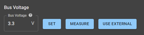
The _Bus Voltage_ section enables users to configure the operational voltage of the bus within a range of 0.8 to 3.3 V. Once the desired voltage is specified, pressing the _SET_ button applies the new setting. Additionally, users can measure the bus voltage and choose to use an external power source. Using an external source is equivalent to measuring the voltage and setting it to match the external supply.

<figure><img src="/files/I3C_busVoltage.png" alt=""><figcaption><p>Bus Voltage sub-panel</p></figcaption></figure>

## Private Transactions

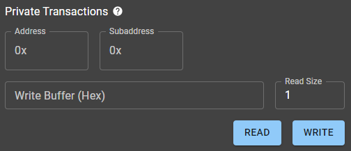
The Private Transactions segment is dedicated to I2C read/write transfers.

1. **Address and Subaddress**: Positioned at the top, users can input these in hexadecimal format.
2. **Write Buffer and Read Size**: The subsequent row houses fields to specify the payload (in hexadecimal) and the byte count for reading.
3. **Read and Write Buttons**: Positioned on the final row, these buttons execute the aforementioned operations.

<figure><img src="/files/image%20(33).png" alt=""><figcaption><p>Private Transactions sub-panel.</p></figcaption></figure>

## Common Command Code (CCC) Operations

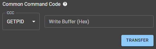
The CCC sub-panel sends I3C Common Command Codes. It has a dropdown menu, a textbox and a TRANSFER button.

<figure><img src="/files/image%20(34).png" alt=""><figcaption><p>Common Command Code sub-panel</p></figcaption></figure>

The BMC App currently supports the following CCC.

<table><thead><tr><th width="228">CCC command</th><th width="504">Description</th></tr></thead><tbody><tr><td>GETBCR</td><td>Get the Bus Characteristics Register</td></tr><tr><td>GETDCR</td><td>Get the Device Characteristics Register</td></tr><tr><td>GETPID</td><td>Get Provisioned ID</td></tr><tr><td>GETMRL</td><td>Get Max Read Length</td></tr><tr><td>GETMWL</td><td>Get Max Write Length</td></tr><tr><td>DIRECT SETMRL</td><td>Set Max Read Length</td></tr><tr><td>DIRECT SETMWL</td><td>Set Max Write Length</td></tr></tbody></table>

Notes:

* The Write Buffer is relevant only for CCC commands that send data, such as DIRECT SETMRL and DIRECT SETMWL.
* New versions of the app add more CCC commands, so this table is a reference only. Download the latest version of Mission Control 2 for the current list.