

Binho Pulsar: Hardware reference
Ports and power domains, electrical ratings, target voltage, pinout and status LEDs of the Binho Pulsar.
Ports and Power Domains
Section titled “Ports and Power Domains”The Pulsar has a USB Type-C port at the rear and four ports at the front for the device under test.
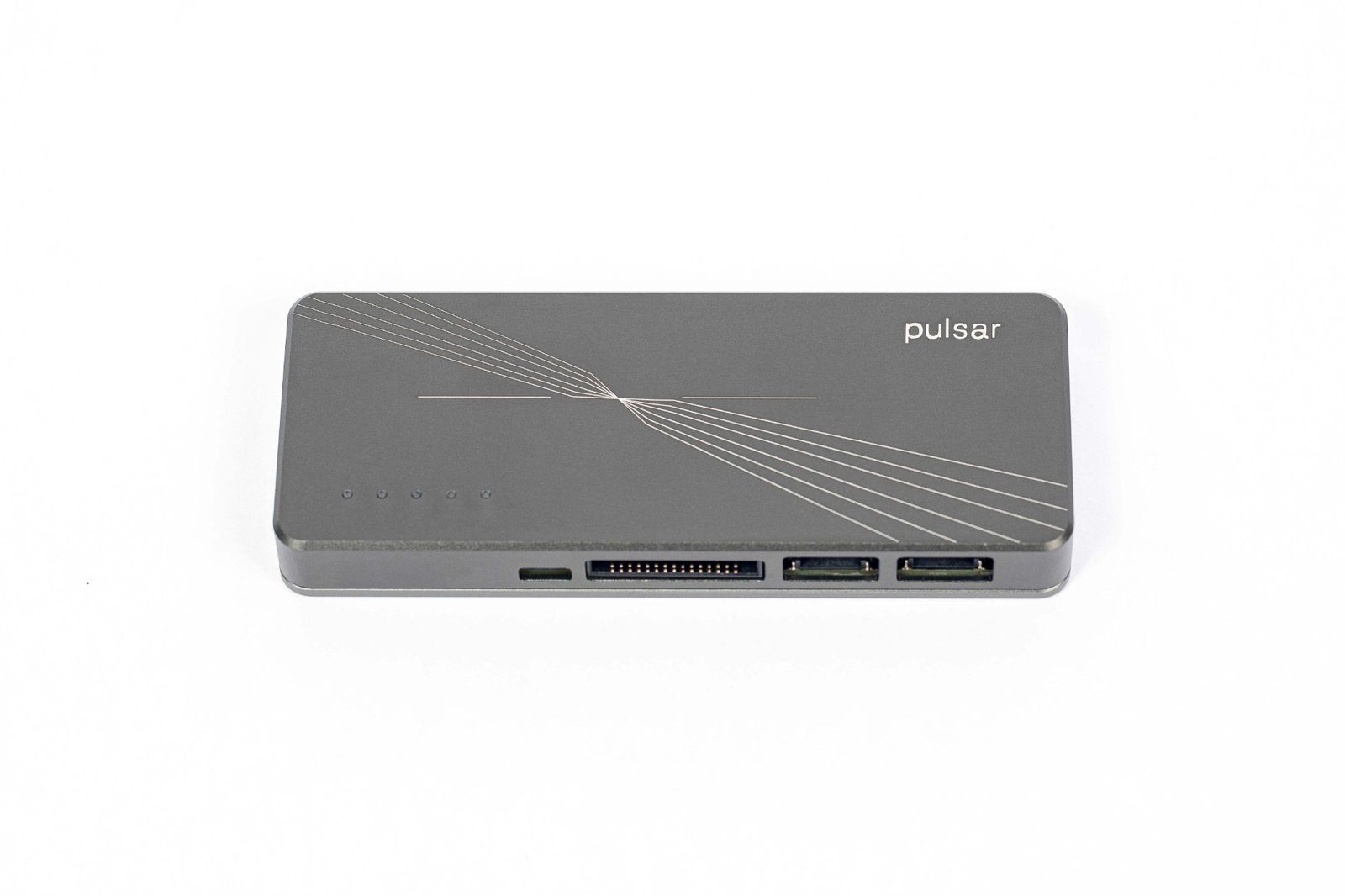
The four front ports.
| Port | Connector | Signals |
|---|---|---|
| USB | USB Type-C | Host PC link and power |
| Multifunction Port | 2 × 15 pin, 1.27 mm pitch | I2C bus B, SPI, UART, 6 GPIO, 1-Wire (Nova compatibility mode) |
| Dedicated I2C Port | 4-pin JST SH (Qwiic compatible) | I2C bus A |
| RS-485 Port | 4-pin JST PH, 2 mm pitch | RS-485 A and B, +5 V |
| CAN-FD Port | 4-pin JST PH, 2 mm pitch | CAN+ and CAN−, +5 V |
The front ports sit on two power domains. Both share ground with each other and with the host PC.
| Power domain | Ports | Voltage |
|---|---|---|
| Multifunction Power Domain | Multifunction Port, Dedicated I2C Port | 1.2 V to 3.3 V set from software, or 0 V (off); up to 200 mA |
| Differential Power Domain | RS-485 Port, CAN-FD Port | Fixed +5 V, always on, up to 200 mA |
I2C, SPI, UART and GPIO share one rail, VTARG. Setting the voltage from any of these interfaces sets it for all four. The 1-Wire pin has its own 3.3 V or 5 V rail.
Electrical Ratings
Section titled “Electrical Ratings”Absolute Maximum Ratings
Section titled “Absolute Maximum Ratings”| Parameter | Max |
|---|---|
| USB input voltage | 5.5 V |
| USB input current | 1000 mA |
| Operating temperature | 0 to 70 °C |
| ESD rating | ±4000 V |
| Multifunction and Dedicated I2C ports, any pin except 1-Wire | 4.2 V |
| 1-Wire pin | 5.5 V |
| Multifunction Power Domain output current | 250 mA |
| RS-485 A, B | −15 to +15 V |
| CAN+, CAN− | −42 to +42 V |
| Differential Power Domain output current | 250 mA |
Recommended Operating Conditions
Section titled “Recommended Operating Conditions”| Parameter | Min | Typ | Max |
|---|---|---|---|
| USB input voltage | 4.5 V | 5.0 V | 5.5 V |
| USB input current | n/a | 500 mA | 1000 mA |
| Multifunction Power Domain voltage (input or output) | 1.2 V | 1.8 V | 3.3 V |
| Multifunction Power Domain output current | n/a | 100 mA | 200 mA |
| 1-Wire pin | n/a | 3.3 V | 5.0 V |
| Differential Power Domain output current | n/a | 100 mA | 200 mA |
| RS-485 A, B | −7 V | n/a | 12 V |
| CAN+, CAN− | −12 V | n/a | 12 V |
Target Voltage (VTARG)
Section titled “Target Voltage (VTARG)”If the board has its own supply
Section titled “If the board has its own supply”Do not set a voltage. Tell the Pulsar the rail comes from outside, then read back what it measures:
i2c.use_external_voltage() # stop driving VTARG, follow the targetprint(i2c.get_bus_voltage(), "mV") # the voltage measured on VTARGMission Control 3 does not store the voltage across power cycles. Only the SDKs can (persist=True).
Pinout Guide
Section titled “Pinout Guide”Multifunction Port (2 × 15)
Section titled “Multifunction Port (2 × 15)”| Pin | Name | Function | Pin | Name | Function |
|---|---|---|---|---|---|
| 1 | SCL | I2C clock (bus B) | 2 | GND | Ground |
| 3 | SDA | I2C data (bus B) | 4 | GND | Ground |
| 5 | RX | UART receive | 6 | GND | Ground |
| 7 | TX | UART transmit | 8 | GND | Ground |
| 9 | RTS | UART ready to send | 10 | GND | Ground |
| 11 | CTS | UART clear to send | 12 | GND | Ground |
| 13 | MOSI | SPI data out (SDO) | 14 | GND | Ground |
| 15 | MISO | SPI data in (SDI) | 16 | GND | Ground |
| 17 | CLK | SPI clock | 18 | GND | Ground |
| 19 | CS0 | SPI chip select 0 or GPIO | 20 | CS1 | SPI chip select 1 or GPIO |
| 21 | CS2 | SPI chip select 2 or GPIO | 22 | CS3 | SPI chip select 3 or GPIO |
| 23 | GPIO1 | General-purpose I/O | 24 | GPIO2 | General-purpose I/O |
| 25 | GPIO3 | General-purpose I/O | 26 | GPIO4 | General-purpose I/O |
| 27 | GPIO5 | General-purpose I/O | 28 | GPIO6 | General-purpose I/O |
| 29 | VTARG | Target voltage (Multifunction Power Domain) | 30 | 1WIRE | 1-Wire bus |
Dedicated I2C Port (Qwiic)
Section titled “Dedicated I2C Port (Qwiic)”| 1 - GND | 2 - VTARG | 3 - SDA (bus A) | 4 - SCL (bus A) |
|---|
RS-485 Port
Section titled “RS-485 Port”| 1 - A (non-inverting) | 2 - B (inverting) | 3 - +5 V | 4 - GND |
|---|
CAN-FD Port
Section titled “CAN-FD Port”| 1 - CAN− | 2 - CAN+ | 3 - +5 V | 4 - GND |
|---|
The RS-485 and CAN-FD ports use the same 2 mm JST PH connector, so their cables are interchangeable. For custom fixtures: the Multifunction Port is a standard 2 × 15, 1.27 mm IDC header, and the enclosure has two M3 mounting holes.
Status LEDs
Section titled “Status LEDs”The Pulsar has 5 RGB status LEDs. They show the device mode, its state and bus traffic.