I2C
I2C, which stands for Inter-Integrated Circuit, is a de-facto standard protocol for inter-chip communication widely used for attaching lower-speed peripheral ICs to processors and MCU in short-distance, intra-board communication.
With a similar approach as SPI, Binho Mission Control presents a streamlined yet potent interface to operate the I2C protocol. The Command Panel is divided into three segments: settings, selection of target devices by address, and execution of I2C transactions.
I2C command panel for Supernova and Pulsar.
Settings
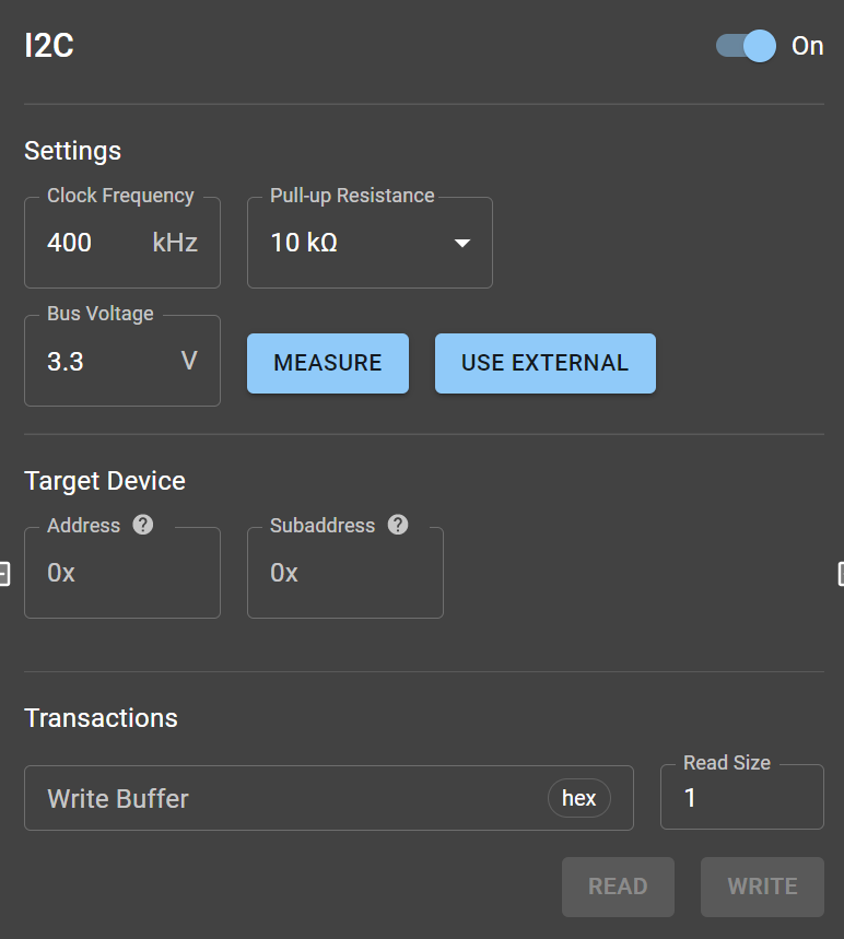
Section titled “Settings”.png)
Settings segment for Nova.
The Settings segment allows users to adjust the following parameters:
| Parameter | Nova values | Supernova and Pulsar values | Comment |
|---|---|---|---|
| Clock Frequency | 100 kHz to 3.4 MHz | 100 kHz to 1 MHz | 4 values available if Non-Standard Frequencies switch is off (for Nova). |
| Internal Pull-Up Resistors | On/Off | 150 Ω to 10 kΩ | Nova pull-up resistor value is fixed. |
| Bus Voltage | 3.3 V | 1.2 V to 3.3 V | In Supernova and Pulsar, users can measure voltage and select an external power source. |
Notes:
- Clock Frequency: The Binho Nova and Binho Supernova facilitate I2C bus clock frequencies ranging from 100 kHz to 3.4 MHz, covering all typical operating modes. Enabling the “Non-Standard Frequencies” option lets users input any desired clock frequency within this range.
- Open Drain Configuration: I2C’s electronic-level execution employs an open-drain configuration, necessitating at least one pull-up resistor for the SDA and SCL pins. The app allows users to activate the in-built pull-up resistors in the Binho Nova.
Target Device
Section titled “Target Device”The app simplifies device detection on the I2C bus. Clicking the “Address” textbox prompts the host adapter to scan for connected devices, listing them for easy selection. Alternatively, users can manually input an address (in hexadecimal).
.png)
Target Device segment for Nova
Featured parameters and allowed values:
| Parameter | Admited values | Comment |
|---|---|---|
| Address | Hexadecimal | Byte grouped. |
| Address format | 7-bit, 8-bit. | |
| Subaddress | Hexadecimal | Optional. |
Notes:
- Address Formats: Both 7-bit and 8-bit address lengths are accommodated. The former uses its initial bit to discern between read and write operations, while the latter assigns distinct addresses for both procedures.
- Subaddress: This optional parameter can pinpoint a specific device register or a memory cell.
Transactions
Section titled “Transactions”Transactions segment
This segment is dedicated to I2C read/write transfers:
- Write Buffer: Users enter the data payload meant for the target device here, in hexadecimal format grouped by byte packets. The WRITE button confirms the transaction.
- Read Size: Specifies the byte amount to be retrieved from the target device. Initiating a read operation is as simple as pressing the READ button.
Real-world Example
Section titled “Real-world Example”The Onsemi CAT24C512 is an I2C EEPROM 512 kb memory that supports Standard, Fast, and Fast-Plus modes. To our knowledge, it lacks pull-up resistors for its SCL and SDA pins, se we activate them via the I2C command panel. We also select a clock frequency of 400 kHz (Fast mode).
When we place the cursor within the “Address” input box, the app automatically detects the memory at address 0x50. We write the payload 0xDE.AD.BE.EF to the subaddress 0xAB.CD. Subsequently, altering the subaddress to 0xAB.CB and requesting an 8-byte read yields the result 0xFF.FF.DE.AD.BE.EF.FF.FF – precisely what we anticipated based on the datasheet’s default register values.
.png)
Write and Read transactions performed with an EEPROM memory.