UART
UART, short for Universal Asynchronous Receiver-Transmitter, is a fundamental serial communication protocol widely used in electronics. The Binho Mission Control app facilitates seamless interaction with the UART protocol, providing users with an intuitive interface for setting up and executing UART communication.
Command Panel Overview
Section titled “Command Panel Overview”When the UART protocol is selected and activated, the Command Panel is divided into three main sections: Bus Voltage, Settings, and Transactions.
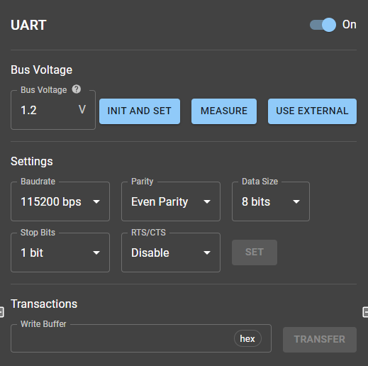
Screenshot of the UART command panel
Bus Voltage
Section titled “Bus Voltage”This section allows users to configure and monitor the UART bus voltage. It includes the following functionalities:
- Set Voltage: Users can set the bus voltage (from 1.2 V to 3.3 V) by specifying the desired value.
- Measure Voltage: Measure the current voltage on the bus.
- Use External Voltage: Select an external voltage source for powering the UART bus.*
Settings
Section titled “Settings”The Settings section provides options for configuring key UART parameters, allowing users to adjust the communication to match the requirements of their target devices:
| Parameter | Admitted Values | Description |
|---|---|---|
| Baudrate | 11 available values (e.g., 115200, 19200) | Communication speed in bits per second. |
| Parity | Even, Odd or No Parity | Error-checking mechanism. |
| Data Size | 7 bits or 8 bits | Number of bits per word. |
| Stop Bits | 1 or 2 | Number of stop bits. |
| RTS/CTS | Enabled, Disabled | Hardware flow control option. |
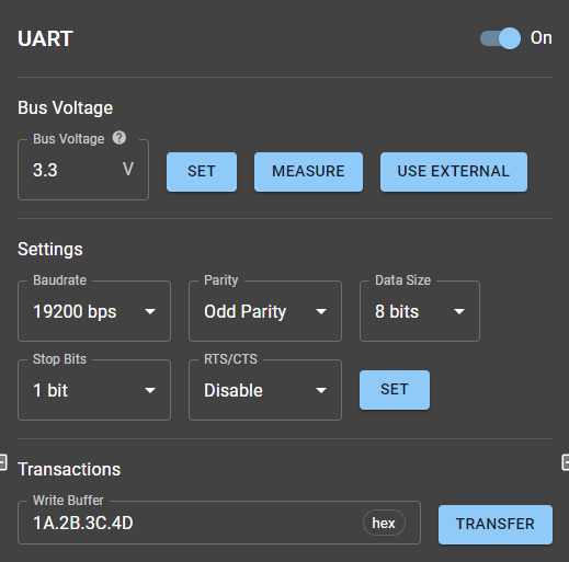
Example: In the provided screenshots, one configuration uses a baud rate of 115200 bps with even parity while another uses 19200 bps, odd parity, and 8-bit data size (see below).
Transactions
Section titled “Transactions”The Transactions section is where users define and execute data transfers between the UART interface and the connected device. It includes:
- Write Buffer: Input field for specifying the data to send (e.g.,
1A.2B.3C.4D). - Transfer Button: Executes the data transmission.
- Incoming Data: When a target sends data to the host adapter, is received as a notification shown in the BMC App’s transaction log.
Another screenshot of the UART panel
Real-world Example
Section titled “Real-world Example”Echo/Loopback Test
Section titled “Echo/Loopback Test”A loopback test involves connecting the RX and TX pins directly. This simple yet effective diagnostic tool ensures that data sent is received back correctly.
Example:
- Configure UART with a baud rate of 19200 bps, odd parity, and an 8-bit data size.
- Input the payload
1A.2B.3C.4Din the Write Buffer and click TRANSFER. - The terminal log shows:
- Data
1A.2B.3C.4Dsent successfully. - Notification: The same data is received, confirming proper operation.
- Data
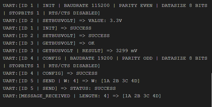
Terminal view showing some transactions performed in the echo test
*When USE EXTERNAL button is pressed, what happens under the hood is that the host adapter measures the voltage in VTAR and then sets the bus voltage to that value using its internal circuitry.